Bancada Didática de sistemas de energia de rede inteligente com SCADA Edibon AEL CPSS-01S
Modelo:AEL CPSS-01S

Modelo:AEL CPSS-01S
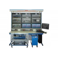
A Bancada Didática de Sistemas de Energia e Rede Inteligente com SCADA Edibon AEL-CPSS-01S é um sistema avançado de ensino desenvolvido pela Edibon para o estudo de redes elétricas inteligentes (smart grids) e sistemas de energia com supervisão e controle em tempo real.
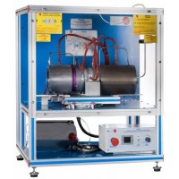
Trata-se de uma solução didática voltada para cursos de engenharia elétrica, energia e automação, permitindo a análise prática de geração, distribuição e gerenciamento inteligente de energia elétrica.
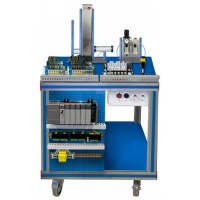
O equipamento integra sensores elétricos para medição de tensão, corrente, potência e energia, além de sistemas de controle e monitoramento baseados em tecnologia SCADA. Essa integração possibilita a visualização e análise em tempo real dos parâmetros do sistema elétrico, permitindo a simulação de diferentes cenários operacionais, como variações de carga, falhas e estratégias de gerenciamento energético.
A operação é realizada por meio de software SCADA dedicado, que oferece interface gráfica completa para supervisão, aquisição de dados e controle do sistema. O usuário pode monitorar variáveis, registrar dados, gerar relatórios e realizar experimentos automatizados, aumentando significativamente a produtividade em laboratório e proporcionando uma experiência prática alinhada às aplicações industriais reais.
A bancada apresenta construção robusta, com módulos didáticos montados em estrutura metálica resistente, projetada para uso intensivo em ambientes educacionais e laboratoriais. Os componentes são organizados de forma didática, facilitando a compreensão dos sistemas elétricos e garantindo segurança durante a operação.
Como solução completa para ensino e pesquisa em redes inteligentes, a AEL-CPSS-01S oferece alto nível de confiabilidade e desempenho. O equipamento contribui para a formação de profissionais capacitados na área de energia elétrica, automação e smart grids, preparando-os para os desafios da modernização dos sistemas energéticos.